In the circuit shown in the figure, the transistors $M_{1}$ and $M_{2}$ are operating in saturation. The channel length modulation coefficients of both the transistors are non-zero. The transconductance of the $\text{MOSFETs}$ $M_{1}$ and $M_{2}$ are $g_{m1}$ and $g_{m2}$, respectively, and the internal resistance of the $\text{MOSFETs}$ $M_{1}$ and $M_{2}$ are $r_{01}$ and $r_{02}$, respectively.
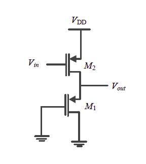
Ignoring the body effect, the $\text{ac}$ small signal voltage gain $\left ( \partial V_{out}/\partial V_{in} \right )$ of the circuit is
- $-g_{m2}\left ( r_{01}\left | \right |r_{02}\right )$
- $-g_{m2}\left ( \frac{1}{g_{m1}}\left | \right |r_{02} \right )$
- $-g_{m1}\left ( \frac{1}{g_{m2}}\left | \right |r_{01}\left | \right |r_{02} \right )$
- $-g_{m2}\left ( \frac{1}{g_{m1}}\left | \right |r_{01}\left | \right |r_{02} \right )$