The block diagram of a system with one input $u$ and two outputs $y_1$ and $y_2$ is given below.
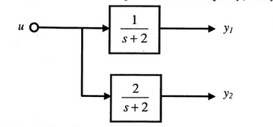
A state space model of the above system in terms of the state vector $\underline{x}$ and the output vector $\underline{y}=\left[\begin{array}{ll}y_1 & y_2\end{array}\right]^T$ is
- $\underline{\dot{x}}=[2] \underline{x}+[1] u ; \quad \underline{y}=\left[\begin{array}{ll}1 & 2\end{array}\right] \underline{x}$
- $\underline{\dot{x}}=[-2] \underline{x}+[1] u ; \quad \underline{y}=\left[\begin{array}{l}1 \\ 2\end{array}\right] \underline{x}$
- $\underline{\dot{x}}=\left[\begin{array}{cc}-2 & 0 \\ 0 & -2\end{array}\right] \underline{x}+\left[\begin{array}{l}1 \\ 1\end{array}\right] u ; \quad \underline{y}=\left[\begin{array}{ll}1 & 2\end{array}\right] \underline{x}$
- $\underline{\dot{x}}=\left[\begin{array}{ll}2 & 0 \\ 0 & 2\end{array}\right] \underline{x}+\left[\begin{array}{l}1 \\ 1\end{array}\right] u ; \quad \underline{y}=\left[\begin{array}{l}1 \\ 2\end{array}\right] \underline{x}$