The circuit shown below is driven by a sinusoidal input $\mathrm{v}_{\mathrm{i}}=\mathrm{V}_{\mathrm{P}} \cos (\mathrm{t} / \mathrm{RC})$. The steady state output $\text{v}_\text{o}$ is
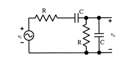
- $\left(\mathrm{V}_p / 3\right) \cos (\mathrm{t / R C})$
- $\left(\mathrm{V}_p / 3\right) \sin (\mathrm{t / R C})$
- $\left(\mathrm{V}_{\mathrm{p}} / 2\right) \cos (\mathrm{t / RC})$
- $\left(\mathrm{V}_p / 2\right) \sin (\mathrm{t / R C})$