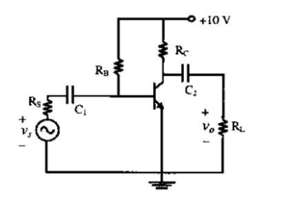
Consider the common emitter amplifier shown below with the following circuit parameters: $\beta=100, g_{m}=0.3861 \mathrm{~A / V}, \mathrm{r}_{\mathrm{o}}=\infty, \mathrm{r}_{\mathrm{x}}=259 \; \Omega, \mathrm{R}_{\mathrm{s}}=1 \; \mathrm{k} \Omega, \mathrm{R}_{\mathrm{B}}=93 \; \mathrm{k} \Omega, \mathrm{R}_{\mathrm{C}}=250 \; \Omega, \mathrm{R}_{\mathrm{t}}=1 \; \mathrm{k} \Omega,\\ \mathrm{C}_{1}=\infty$ and $\mathrm{C}_{2}=4.7\; \mu \mathrm{F}.$
The lower cut-off frequency due to $\mathrm{C}_{2}$ is
- $33.9 \mathrm{~Hz}$
- $27.1 \mathrm{~Hz}$
- $13.6 \mathrm{~Hz}$
- $16.9 \mathrm{~Hz}$