In the following circuit, the comparator output is logic $\text{“1”}$ if $\mathrm{V}_{1}>\mathrm{V}_{2}$ and is logic $\text{“0”}$ otherwise. The D/A conversion is done as per the relation
$V_{\mathrm{DAC}}=\displaystyle{}\sum_{n=0}^{3} 2^{n-1} b_{n}$ Volts, where $b_{3}$ (MSB), $b_{2}, b_{1}$ and $b_{0}$ (LSB) are the counter outputs.
The counter starts from the clear state.
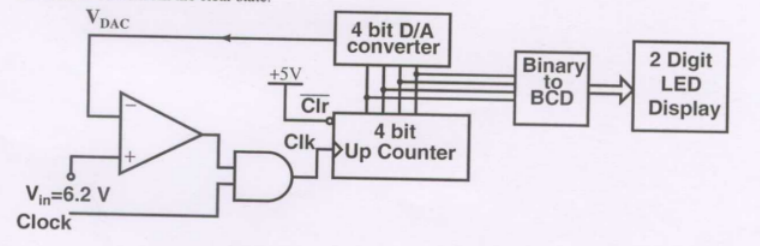
The stable reading of the LED displays is
- $06$
- $07$
- $12$
- $13$