The circuit shown in the figure is used to charge the capacitor $\mathrm{C}$ alternately from two current sources as indicated. The switches $\text{S1}$ and $\text{S2}$ are mechanically coupled and connected as follows:
For $2 n T \leq t<(2 n+1) T, \quad(n=0,1,2, \cdots) \quad \mathrm{S} 1$ to $\mathrm{P} 1$ and $\mathrm{S} 2$ to $\text{P2.}$
For $(2 n+1) T \leq t<(2 n+2) \quad T,(n=0,1,2, \cdots) \quad \mathrm{S} 1$ to $\mathrm{Q} 1$ and $\mathrm{S} 2$ to $\mathrm{Q} 2$.
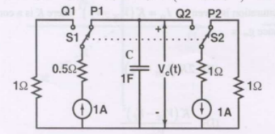
Assume that the capacitor has zero initial charge. Given that $u(t)$ is a unit step function, the voltage $V_{c}(t)$ across the capacitor is given by
- $\displaystyle{}\sum_{n=0}^{\infty}(-1)^{n} t u(t-n T)$
- $\displaystyle{}u(t)+2 \sum_{n=1}^{\infty}(-1)^{n} u(t-n T)$
- $\displaystyle{}t u(t)+2 \sum_{n=1}^{\infty}(-1)^{n}(t-n T) u(t-n T)$
- $\displaystyle{}\sum_{n=0}^{\infty}\left[0.5-e^{-(t-2 n T)}+0.5 e^{-(t-2 n T-T)}\right]$