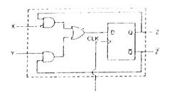
A sequential circuit using $D$ Flip-Flop and logic gates is shown in figure, where $X$ and $Y$ are the inputs and $Z$ is the output. The circuit is
- $S-R$ Flip-Flop with inputs $X=R$ and $Y=S$
- $S-R$ Flip-Flop with inputs $X=S$ and $Y=R$
- $J-K$ Flip-Flop with inputs $X=J$ and $Y=K$
- $J-K$ Flip-Flop with inputs $X=K$ and $Y=J$