The decoding circuit shown in the figure is has been used to generate the active low chip select signal for a microprocessor peripheral. (The address lines are designated as $\mathrm{AO}$ to $\mathrm{A} 7$ for $\mathrm{l} / \mathrm{O}$ addresses)
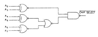
The peripheral will correspond to $1 / \mathrm{O}$ addresses in the range
- $60 \; \mathrm{H}$ to $63 \; \mathrm{H}$
- $\mathrm{A} 4$ to $\mathrm{A} 7 \; \mathrm{H}$
- $30 \; \mathrm{H}$ to $33 \; \mathrm{H}$
- $70 \; \mathrm{H}$ to $73 \; \mathrm{H}$