In the circuit shown, diodes $D_{1}, D_{2}$ and $D_{3}$ are ideal, and the inputs $E_{1} , E_{2}$ and $E_{3}$ are $“0\: V”$ for logic $‘0’$ and $“10\: V”$ for logic $‘1’$. What logic gate does the circuit represent?
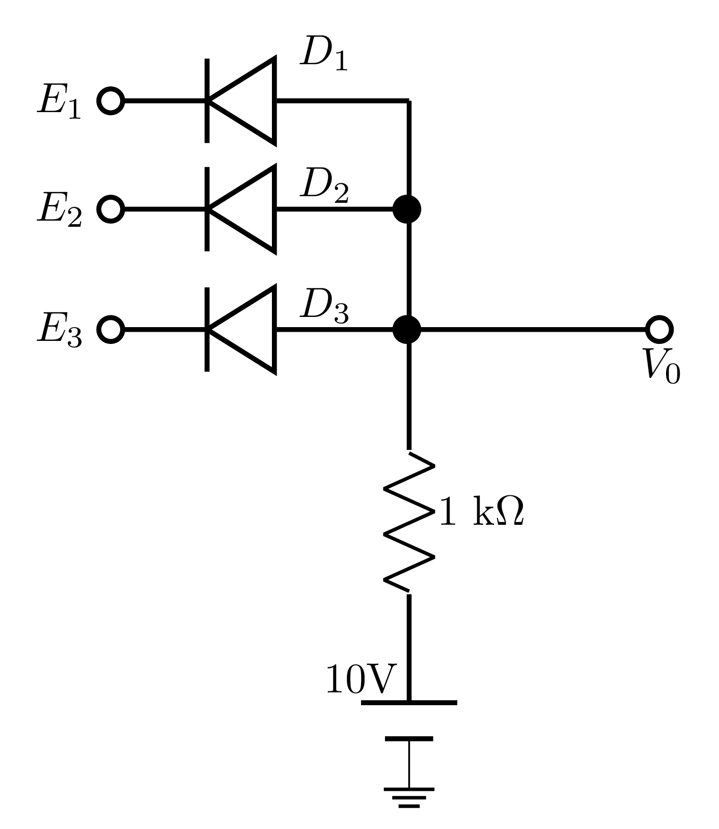
- $3$-input OR gate
- $3$-input NOR gate
- $3$-input AND gate
- $3$-input XOR gate