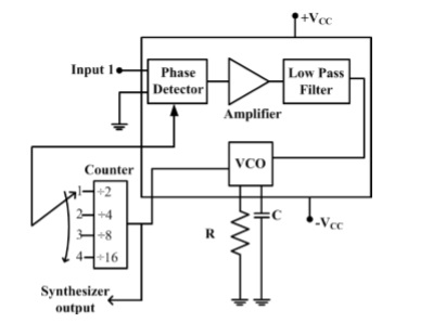
The block diagram of a frequency synthesizer consisting of a Phase Locked Loop (PLL) and a divide-by-$N$ counter (comprising $\div 2, \div 4, \div 8, \div 16$ outputs) is sketched below. The synthesizer is excited with a $5$ kHz signal (Input $1$). The free-running frequency of the PLL is set to $20$ kHz. Assume that the commutator switch makes contacts repeatedly in the order $1-2-3-4$.
The corresponding frequencies synthesized are:
- $10 \: kHz, 20 \: kHz, 40 \: kHz, 80 \: kHz$
- $20 \: kHz, 40 \: kHz, 80 \: kHz, 160 \: kHz$
- $80 kHz, 40 \: kHz, \: 20 kHz, \: 10 kHz$
- $160 \: kHz, 80 \: kHz, 40 \: kHz, 20 \: kHz$