recategorized by
745 views
0 0 votes

The electrical system shown in the figure converts input source current $i_{s}(t)$ to output voltage $v_{o}(t)$
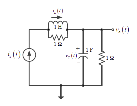
Current i $i_{L}(t)$ in the inductor and voltage $v_{c}(t)$ across the capacitor are taken as the state variables, both assumed to be initially equal to zero, i.e., $i_{L}(0) =0$ and $v_{c}(0)=0$. The system is

  1. completely state controllable as well as completely observable
  2. completely state controllable but not observable
  3. completely observable but not state controllable
  4. neither state controllable nor observable

Please log in or register to answer this question.

Answer:
Position:
Show:

Related questions

0 0 votes
0 0 answers
274
274 views
admin asked Sep 27, 2022
274 views
The block diagram of a linear time invariant system is given in the figure isWrite down the state variable equations for the system in matrix form assuming the state vect...
1 1 vote
0 0 answers
488
488 views
admin asked Sep 3, 2022
488 views
The block diagram of a system with one input $u$ and two outputs $y_1$ and $y_2$ is given below.A state space model of the above system in terms of the state vector $\und...
1 1 vote
0 0 answers
537
537 views
admin asked May 20, 2023
537 views
The state equation of a second order system is$\dot{\boldsymbol{x}}(t)=\mathrm{A} \boldsymbol{x}(t), \; \boldsymbol{x}(0)$ is the initial condition.Suppose $\lambda_1$ an...
1 1 vote
0 0 answers
826
826 views
Arjun asked Feb 19, 2021
826 views
The block diagram of a feedback control system is shown in the figureThe transfer function $\dfrac{Y{\left ( s \right )}}{X {\left ( s \right )}}$ of the system is$\frac{...

Add Synced Question

×