In the figure, the output of the oscillator, $\mathrm{V}_{1}$ has $10 \mathrm{~V}$ peak amplitude with zero DC value. The transfer characteristic of the Schmitt inverter is also shown in the figure is. Assume that the JK flip-flop is reset at time $t=0$.
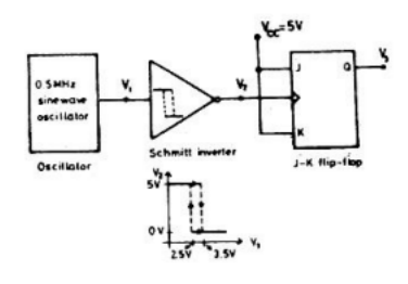
- What is the period and duty cycle of the waveform $\mathrm{V}_{2}$ ?
- What is the period and duty cycle of the waveform $\mathrm{V}_{3}$ ?
- Sketch $\mathrm{V}_{1}, \mathrm{~V}_{2}$ and $\mathrm{V}_{3}$ for the duration $0 \leq t \leq 6 \; \mu s$. Clearly indicate the exact timings when the waveforms $\mathrm{V}_{2}$ and $\mathrm{V}_{3}$ make high-to-low and low-to-high transitions.