An electrical system and its signal-flow graph representations are shown in the figure respectively. The values of $G_{2}$ and $H$, respectively, are
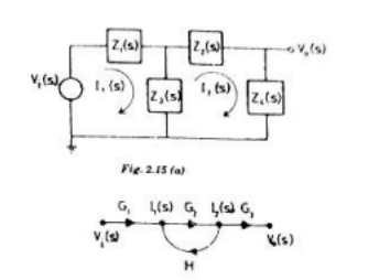
- $\frac{Z_3(s)}{Z_2(s)+Z_3(s)+Z_4(s)}, \frac{-Z_3(s)}{Z_1(s)+Z_3(s)}$
- $\frac{-Z_3(s)}{Z_2(s)-Z_3(s)+Z_4(s)}, \frac{-Z_3(s)}{Z_1(s)+Z_3(s)}$
- $\frac{Z_3(s)}{Z_2(s)+Z_3(s)+Z_4(s)}, \frac{Z_3(s)}{Z_1(s)+Z_3(s)}$
- $\frac{-Z_3(s)}{Z_2(s)-Z_3(s)+Z_4(s)}, \frac{Z_3(s)}{Z_1(s)+Z_3(s)}$