In the TTL circuit in the figure, $\mathrm{S}_{2}$ to $\mathrm{S}_{0}$ are select lines and $\text{X}_{7}$ to $\text{X}_{0}$ are input lines. $\text{S}_{0}$ and $\text{X}_{0}$ are LSBs. The output $Y$ is
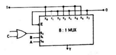
- indeterminate
- $\mathrm{A} \oplus \mathrm{B}$
- $\overline{\mathrm{A} \oplus \mathrm{B}}$
- $\overline{\mathrm{C}} \cdot(\overline{\mathrm{A} \oplus \mathrm{B}})+\mathrm{C} \cdot(\mathrm{A} \oplus \mathrm{B})$