• recategorized by
656 views
0 0 votes

In the circuit shown below, the op-amp is ideal and Zener voltage of the diode is $2.5\: volts$. At the input, unit step voltage is applied, i.e. $v_{IN}\left ( t \right ) = u\left ( t \right )\:volts$. Also, at $t = 0$, the voltage across each of the capacitors is zero.
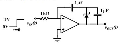
                         

The time $t$, in milliseconds, at which the output voltage $v_{OUT}$ crosses $-10\: V$ is 

  1. $2.5$
  2. $5$
  3. $7.5$
  4. $10$

Please log in or register to answer this question.

Answer:
Position:
Show:

Related questions

0 0 votes
0 0 answers
454
454 views
gatecse asked Feb 19, 2018
454 views
The circuit shown in the figure is used to provide regulated voltage $(5 V)$ across the $1\: k\Omega$ resistor. Assume that the Zener diode has a constant reverse breakdo...
0 0 votes
0 0 answers
523
523 views
Milicevic3306 asked Mar 27, 2018
523 views
In the opamp circuit shown, the Zener diodes $Z1$ and $Z2$ clamp the output voltage $V_{0}$ to $+5V$ or $-5 V$. The switch $S$ is initially closed and is opened at time $...
0 0 votes
0 0 answers
481
481 views
gatecse asked Feb 19, 2018
481 views
A solar cell of area $1.0\:cm^{2},$ operating at $1.0$ sun intensity, has a short circuit current of $20\: mA$, and an open circuit voltage of $0.65\: V$. Assuming room t...
0 0 votes
0 0 answers
494
494 views
gatecse asked Feb 19, 2018
494 views
Red (R), Green(G) and Blue (B) Light Emitting Diodes (LEDs) were fabricated using $\text{p-n}$ junctions of three different inorganic semiconductors having different band...

Add Synced Question

×