recategorized by
1,874 views
1 1 vote

Consider the CMOS circuit shown, where the gate voltage $V_{G}$ of the $\text{n-MOSFET}$ is increased from zero, while the gate voltage of the $\text{p-MOSFET}$ is kept constant at $3 \mathrm{~V}$. Assume that, for both transistors, the magnitude of the threshold voltage is $1 \mathrm{~V}$ and the product of the transconductance parameter and the $\text{(W/L)}$ ratio, i.e. the quantity $\mu C_{o r}(\mathrm{~W} / \mathrm{L})$, is $1 \mathrm{~mA} \cdot \mathrm{V}^{-2}$.
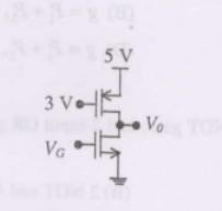

Estimate the output voltage $V_{0}$ for $V_{G}=1.5 \mathrm{~V}$. [Hint: Use the appropriate current-voltage equation for each MOSFET, based on the answer to Q. $57.]$

  1. $4-\frac{1}{\sqrt{2}} \mathrm{~V}$
  2. $4+\frac{1}{\sqrt{2}} \mathrm{~V}$
  3. $4-\frac{\sqrt{3}}{2} \mathrm{~V}$
  4. $4+\frac{\sqrt{3}}{2} \mathrm{~V}$

1 Answer

Position:
Show:

Related questions

1 1 vote
0 0 answers
642
642 views
admin asked Sep 19, 2022
642 views
In the CMOS inverter circuit shown, if the transconductance parameters of the NMOS and PMOS transistors are $k_{n}=k_{p}=\mu_{n} C_{o x} \dfrac{W_{n}}{L_{n}}=\mu_{p} C_{o...
1 1 vote
0 0 answers
604
604 views
admin asked Sep 15, 2022
604 views
Consider the CMOS circuit shown, where the gate voltage $V_{G}$ of the $\text{n-MOSFET}$ is increased from zero, while the gate voltage of the $\text{p-MOSFET}$ is kept c...
1 1 vote
0 0 answers
505
505 views
admin asked Sep 15, 2022
505 views
Consider the following two statements about the internal conditions in an n-channel MOSFET operating in the active region.$\qquad \qquad \text{S1:}$ The inversion charge ...
0 0 votes
0 0 answers
195
195 views
admin asked Sep 29, 2022
195 views
In the $\text{CMOS}$ inverter circuit shown in the figure is the input Vi makes a transition from $\mathrm{V}_{\mathrm{OL}}(=0 \mathrm{~V})$ to $\mathrm{V}_{\mathrm{OH}}(...

Add Synced Question

×