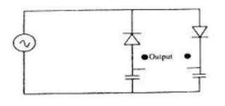
0 votes 0 votes The circuit shown in the figure is best described as a bridge rectifier ring modulator frequency discriminatory voltage doubler Others gate2003-ec + – admin asked Sep 26, 2022 • edited Nov 30, 2023 by makhdoom ghaya admin 46.4k points 116 views answer comment Share Follow See all 0 reply Please log in or register to add a comment.