The inputs to a digital circuit shown in the figure is are the external signals $A, B$ and $C$.
$(\overline{\mathrm{A}}, \overline{\mathrm{B}}$ and $\overline{\mathrm{C}}$ are not available). The $+5 \mathrm{~V}$ power supply (logic $1$) and the ground (logic $0$) are also available. The output of the circuit is $\mathrm{X}=\overline{\mathrm{A}} \mathrm{B}+\overline{\mathrm{A}} \; \overline{\mathrm{B}} \; \overline{\mathrm{C}}$.
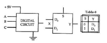
- Write down the output function in its canonical SOP and POS forms.
- Implement the circuit using only two $2:1$ multiplexers shown in the figure where $S$ is the data-select line, $D_{0}$ and $D_{1}$ are the input data lines and $Y$ is the output line. The function table for the multiplexer is in given Table.