The propagation delays of the $\text{XOR}$ gate, $\text{AND}$ gate and multiplexer $\text{(MUX)}$ in the circuit shown in the figure are $4\:ns$, $2\:ns$ and $1\:ns$, respectively.
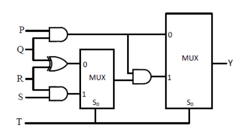
If all the inputs $\text{P, Q, R, S and T}$ are applied simultaneously and held constant, the maximum propagation delay of the circuit is
- $3\:ns$
- $5\:ns$
- $6\:ns$
- $7\:ns$