The figure is shows the block diagram of phase-locked-loop $\text{(PLL)}$ in the locked condition.
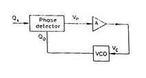
The output voltage of the phase detector is given by
\[
\mathrm{V}_{p}=\mathrm{K}_{d}\left(\phi_{i}-\phi_{0}\right),
\]
where $\phi_{1}=$ phase of the input signal, and
$\qquad \; \; \phi_{0}=$ the phase of the output Voltage Controlled Oscillator $\text{(VOC)}$.
The value of $\mathrm{K}_{d}$ is $1 \mathrm{Volt} / \mathrm{radian}$,
The frequency deviation of the $\text{VCO}$ output is,
\[
\Delta f_{\mathrm{o}}=\mathrm{K}_{f} \mathrm{~V}_{\mathrm{C}}
\]
where $\mathrm{V}_{\mathrm{C}}=$ input voltage of the $\mathrm{VCO}$, and
\[
k_{f}=159.15 \mathrm{~Hz} / \text { volt. }
\]
The amplifier $\mathrm{A}$ is a buffer with a voltage gain of unity.
- Derive the transfer function $\phi_{0}(s) / \phi_{i}(s)$.
- Let the loop to be locked for time $t<0$ and $\Phi_{i}$ $(t)=u(t)$ radian, where $u(t)$ is the unit step function. Determine $\Phi_{0}(t)$ for $t>0$.