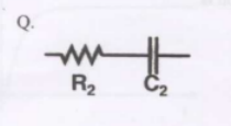
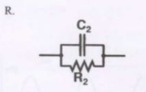
$\text{Group I}$ gives two possible choices for the impedance $\mathrm{Z}$ in the diagram. The circuit elements in $\mathrm{Z}$ satisfy the condition $R_{2} C_{2}>R_{1} C_{1}$. The transfer function $\dfrac{V_{o}}{V_{i}}$ represents a kind of controller. Match the impedances in $\text{Group I}$ with the types of controllers in $\text{Group II.}$
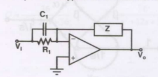
$$\begin{array}{ll} \textbf{Group I} & \textbf{Group II} \\ \text{Q.} & \text{1. PID controller} \\ \text{R.} & \text{2. Lead compensator} \\ & \text{3. Lag compensator} \end{array}$$
- $\text{Q-1, R-2}$
- $\text{Q-1, R-3}$
- $\text{Q-2, R-3}$
- $\text{Q-3, R-2}$