• recategorized by
924 views
0 0 votes

In the circuit shown below, a positive edge-triggered $D$ Flip-Flop is used for sampling input data $D_{in}$ using clock $CK$. The XOR gate output $3.3$ volts for logic HIGH and $0$ volts for logic LOW levels. The data bit and clock periods are equal and the value of $\Delta T/T_{CK}=0.15,$ where the parameters $\Delta T$ and $T_{CK}$ are shown in the figure. Assume that the Flip-Flop and the XOR gate are ideal.
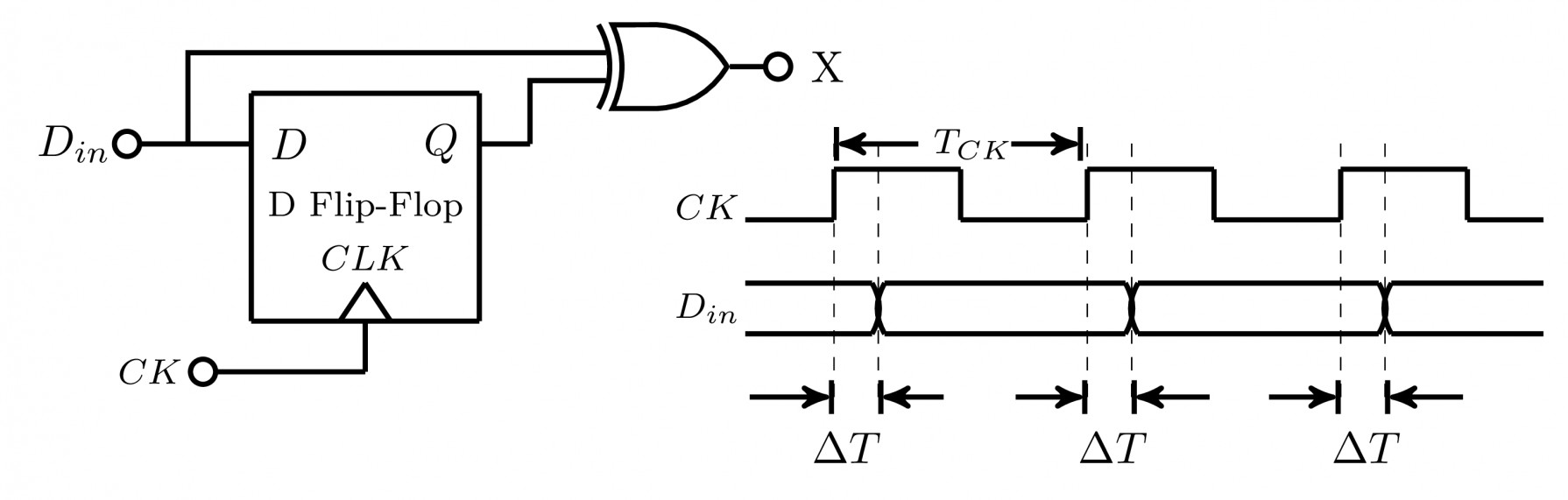
If the probability of input data bit $\left ( D_{in} \right )$ transition in each clock period is $0.3$, the average value (in volts, accurate to two decimal places) of the voltage at node $X$, is _________.

Please log in or register to answer this question.

Answer:
Position:
Show:

Related questions

0 0 votes
0 0 answers
539
539 views
gatecse asked Feb 19, 2018
539 views
A traffic signal cycles from $\text{ GREEN to YELLOW, YELLOW to RED and RED to GREEN.}$ In each cycle, $\text{GREEN}$ is turned on for $70$ seconds,$\text{YELLOW}$ is tur...
2 2 votes
1 1 answer
3.1k
3.1k views
go_editor asked Feb 13, 2020
3,146 views
For the components in the sequential circuit shown below, $t_{pd}$ is the propagation delay, $t_{\text{setup}}$ is the setup-time, and $t_{\text{hold}}$ is the hold time....
0 0 votes
0 0 answers
822
822 views
Milicevic3306 asked Mar 27, 2018
822 views
An SR latch is implemented using TTL gates as shown in the figure. The set and reset pulse inputs are provided using the push-button switches. It is observed that the cir...
0 0 votes
0 0 answers
703
703 views
Milicevic3306 asked Mar 26, 2018
703 views
The circuit shown in the figure is a Toggle Flip FlopJK Flip FlopSR LatchMaster-Slave D Flip Flop

Add Synced Question

×