The operating conditions $(O N=1, O F F=0)$ of three pumps $(x, y, z)$ are to be monitored. $x=1$ implies that pump $X$ is on. It is required that the indicator $\text{(LED)}$ on the panel should glow when a majority of the pumps fail.
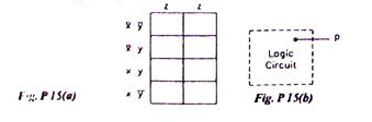
- Enter the logical values in the $K$-map in the format shown in figure. Derive the minimal Boolean sum-of- products expression whose output is zero when a majority of the pumps fail.
- The above expression is implemented using logic gates, and point $P$ is the output of this circuit, as shown in given figure, $P$ is at $0 \mathrm{~V}$ when a majority of the pumps fails and is at $5 V$ otherwise. Design a circuit to drive the $\text{LED}$ using this output.
The current through the $\text{LED}$ should be $10 \mathrm{~mA}$ and the voltage drop across it is $1 \mathrm{~V}$. Assume that $P$ can source or sink $10 \mathrm{~mA}$ and a $5 \mathrm{~V}$ supply is available.