• recategorized by
340 views
0 0 votes


Common Data for Questions 71, 72,73:

In the transistor amplifier circuit shown in the figure below, the transistor has the following parameters:
\[ \beta_{\mathrm{DC}}=60, \mathrm{~V}_{\mathrm{BE}}=0.7 \mathrm{~V}, h_{n^{c}} \longrightarrow \infty, h_{f \times} \longrightarrow \infty\]
 The capacitance $\mathrm{C}_{\text {c }}$ can be assumed to be infinite.
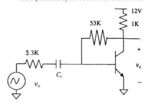

In the figure above, the ground has been shown by the symbol $\nabla$

Under the DC conditions, the collector-to-emitter voltage drop is

  1. $4.8$ Volts
  2. $5.3$ Volts
  3. $6.0$ Volts
  4. $6.6$ Volts

Please log in or register to answer this question.

Answer:
Position:
Show:

Related questions

0 0 votes
0 0 answers
421
421 views
admin asked Oct 2, 2022
421 views
The transistor in the circuit shown in the figure is so biased ($dc$ biasing network is not shown) that the $dc$ collecter current $I_{c}=1 \mathrm{~mA}$. Supply is $V_{c...
1 1 vote
0 0 answers
208
208 views
admin asked Sep 17, 2022
208 views
In the following transistor circuit, $V_{B E}=0.7 \mathrm{~V}, r_{e}=25 \; \mathrm{mV} / I_{E},$ and $\beta$ and all the capacitances are very large.The mid-band voltage ...
0 0 votes
0 0 answers
406
406 views
admin asked Sep 20, 2022
406 views
Common Data for Questions 71, 72,73:In the transistor amplifier circuit shown in the figure below, the transistor has the following parameters:\[ \beta_{\mathrm{DC}}=60, ...
0 0 votes
0 0 answers
192
192 views
admin asked Sep 29, 2022
192 views
A bipolar junction transistor amplifier circuit is shown in the figure is Assume that the current source $\text{I}_{\text {bias}}$ is ideal, and the transistor has vary l...

Add Synced Question

×