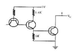
The transistors used in a portion of the TTL gate shown in the figure have a $\beta=100$. The base-emitter voltage of is $0.7 \mathrm{~V}$ for a transistor in active region and $0.75 \mathrm{~V}$ for a transistor in saturation. If the sink current $I=1 \mathrm{~mA}$ and the output is at logic $0,$ then the current $I_{R}$ will be equal to
- $0.65 \mathrm{~mA}$.
- $0.70 \mathrm{~mA}$
- $0.75 \mathrm{~mA}$.
- $1.00 \mathrm{~mA}$