edited by
695 views
0 0 votes

A $4:1$ multiplexer is to be used for generating the output carry of a full adder. $A$ and $B$ are the bits to be added while $C_{in}$ is the input carry and $C_{out}$ is the output carry. $A$ and $B$ are to be used as the select bits with $A$ being the more significant select bit.
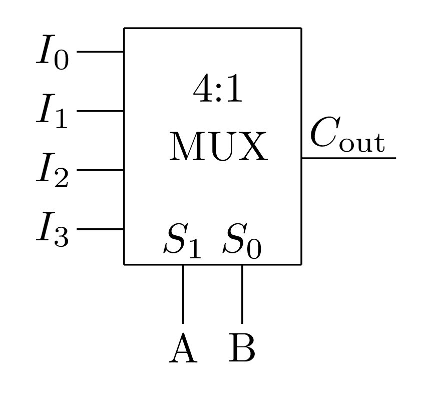
Which one of the following statements correctly describes the choice of signals to be connected to the inputs $I_{0},$ $I_{1},$ $I_{2}$ and $I_{3},$ so that the output is $C_{out}$?

  1. $I_{0}=0, I_{1}=C_{in},I_{2}=C_{in}$ and $I_{3}=1$
  2. $I_{0}=1, I_{1}=C_{in},I_{2}=C_{in}$ and $I_{3}=1$
  3. $I_{0}=C_{in}, I_{1}=0,I_{2}=1$ and $I_{3}=C_{in}$
  4. $I_{0}=0, I_{1}=C_{in},I_{2}=1$ and $I_{3}=C_{in}$

Please log in or register to answer this question.

Answer:
Position:
Show:

Related questions

0 0 votes
0 0 answers
897
897 views
Milicevic3306 asked Mar 27, 2018
897 views
The functionality implemented by the circuit below is$2$-to-$1$ multiplexer $4$-to-$1$ multiplexer$7$-to-$1$ multiplexer$6$-to-$1$ multiplexer
4 4 votes
1 1 answer
1.1k
1.1k views
admin asked Nov 23, 2017
1,094 views
Consider the circuit shown in the figure. The Boolean expression $F$ implemented by the circuit is$\overline{X} \overline{Y} \overline{Z} + X Y +\overline{Y} Z $$\overlin...
2 2 votes
1 1 answer
1.1k
1.1k views
Milicevic3306 asked Mar 26, 2018
1,130 views
An $8$- to $1$ multiplexer is used to implement a logical function $Y$ as shown in the figure. The output $Y$ is given by$Y = A \: \overline{B} \:C+A \: \overline{C} \:D...
2 2 votes
1 1 answer
1.2k
1.2k views
Milicevic3306 asked Mar 26, 2018
1,245 views
Consider the multiplexer based logic circuit shown in the figure.Which one of the following Boolean functions is realized by the circuit?$F= W \overline{S_1} \: \overline...

Add Synced Question

×