Assume that all the digital gates in the circuit shown in the figure are ideal, the resistor $R=10\Omega$ and the supply voltage is $5\:V$. The $D$ flip-flops $D_{1} \:, D_{2} \:, D_{3} \:, D_{4}$ and $D_{5}$ are initialized with logic values $0,1,0,1$ and $0$, respectively. The clocks has a $30\%$ duty cycle.
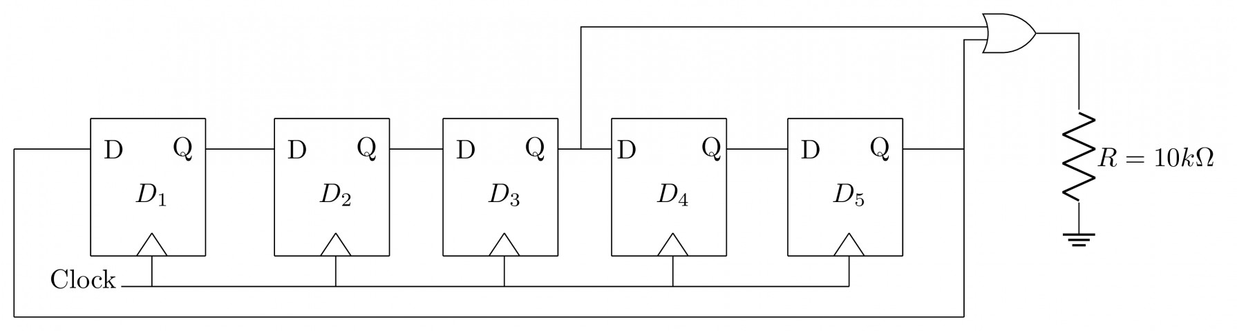
The average power dissipated (in $mW$) in the resistor $R$ is _________