The circuit shown in the figure has $4$ boxes each described by inputs $P, Q, R$ and outputs $Y, Z$ with
\[\begin{array}{l}
Y=P \oplus Q \oplus R \\
Z=R Q+\bar{P} R+Q \bar{P}
\end{array}\]
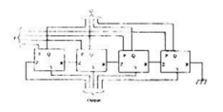
The circuit acts as a
- $4$ bit adder giving $P+Q$
- $4$ bit subtractor giving $P-Q$
- $4$ bit subtractor giving $Q-P$
- $4$ bit adder giving $P+Q+R$